

Quantum Teleportation
Quantum Teleportation
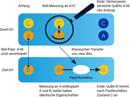
Quantum teleportation via quantum gates is shown in the following two sketches schematically and as a circuit diagram consisting of CNOT, Hadamard and XZ gates [1,2]:

The goal of quantum teleportation is to transfer the state of QuBit C to another QuBit B. Due to the No-Cloning theorem it is however not possible to directly transfer the state of QuBit C to another QuBit without changing the state of QuBit C. The state of QuBit C is initially |QC>:
\Ket{Q_C}=\alpha\Ket{0}+\beta\Ket{1}Therefore three QuBits are required for the execution of a quantum teleportation: QuBit C has the state to be transferred and the other two entangled QuBits (A and B) are used to transfer the state from QuBit C to QuBit B.
Sequence of a quantum teleportation
- Two QuBits A and B are entangled with each other. Bob keeps QuBit B and sends QuBit A to Alice.
- Alice concatenates her QuBit C with the received QuBit A via a CNOT gate and applies an Hadamard gate.
- Alice measures the states of QuBit C and QuBit A.
- Alice communicates the result of the measurements -encoded by two classical bits- via a classical communication channel.
- Depending on the measurement result Bob applies X and/or Z gates to his QuBit B to obtain the original state of QuBit C.
Mathematical description of step 1
The entanglement of QuBit A and B yields:
\Ket{e}=\frac{1}{\sqrt{2}}(\Ket{00}+\Ket{11})=\frac{1}{\sqrt{2}}(\Ket{0}_{A}\Ket{0}_{B}+\Ket{1}_{A}\Ket{1}_{B})Thus together with QuBit C whose one-particle state is to be transferred, the state vector of the total system at 1. is given by:
\Ket{Q_C}\otimes\Ket{e}=\frac{1}{\sqrt{2}}(\alpha\Ket{000}+\alpha\Ket{011}+\beta\Ket{100}+\beta\Ket{111})Excursus: Description of the evolution of the total system.
In order to obtain a mathematical expression for the description of the evolution of the total system starting from the quantum gates used so far, we first investigate a system with two QuBits. We consider the case where QuBit q1 experiences a Hadamard gate while QuBit q0 is left undisturbed [3]:
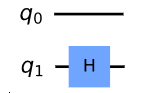
No changes at QuBit q0 are described via the identity matrix I:
I=\begin{bmatrix} 1 & 0\\ 0 & 1 \end{bmatrix}
Matrix G that changes the state vector of both QuBits according to the above circuit is obtained from a tensor product of the matrices I and H:
G=I\otimes H=\begin{bmatrix} H & 0\\ 0 & H \end{bmatrix}=\frac{1}{\sqrt{2}} \Biggl[ \begin{bmatrix} 1 & 1 & 0 & 0\\ 1 & -1 & 0 & 0 \\ 0 & 0 & 1 & 1 \\ 0 & 0 & 1 & -1 \end{bmatrix} \Biggr]
For the used ordering of the entries in the state vector, G is obtained by taking the corresponding matrices in the circuit from top to bottom and combining them from left to right via a tensor product.
Mathematical description of step 2 and explanation of steps 3 and 4
Analogous to the case above with the QuBits q0 and q1, a description of the interaction of QuBit C with QuBit A via a CNOT gate is obtained from a tensor product between the matrices CNOT and I:
G_1 = CNOT\otimes I = \Biggl[\begin{bmatrix} I & 0 & 0 & 0\\ 0 & I & 0 & 0 \\ 0 & 0 & 0 & I \\ 0 & 0 & I & 0 \end{bmatrix} \Biggr]
The description of the subsequent application of a Hadamard gate to QuBit C is obtained from the tensor product between the matrices H, I and I:
G_2 = \frac{1}{\sqrt{2}}\Biggl[ \begin{bmatrix} I & 0 & I & 0\\ 0 & I & 0 & I \\ I & 0 & -I & 0 \\ 0 & I & 0 & -I \end{bmatrix} \Biggr]
The state vector of the total system at 2. is obtained by applying G2G1 (normal matrix product!) to the state vector of the total system at 1.:
(G_2 \cdot G_1) (\Ket{Q_C} \otimes \Ket{e}) = \\ \frac{1}{\sqrt{2}} (H \otimes I \otimes I) \cdot (CNOT \otimes I) (\alpha\Ket{000}+\alpha\Ket{011}+\beta\Ket{100} + \beta\Ket{111}) = \\ \frac{1}{\sqrt{2}} (H \otimes I \otimes I) (\alpha\Ket{000} + \alpha\Ket{011} + \beta\Ket{101} + \beta\Ket{110}) = \\ \frac{1}{2}(\alpha(\Ket{000} + \Ket{011} + \Ket{100} + \Ket{111}) + \beta(\Ket{001} + \Ket{010} - \Ket{101} - \Ket{110})) = \\ \frac{1}{2}(\color{green}{\Ket{00}}\color{black}{(}\color{blue}{\alpha\Ket{0} + \beta\Ket{1}}\color{black}{)+} \color{green}{\Ket{01}}\color{black}{(}\color{blue}{\alpha\Ket{1} + \beta\Ket{0}}\color{black}{)+}\color{green}{\Ket{10}}\color{black}{(}\color{blue}{\alpha\Ket{0}-\beta\Ket{1}}\color{black}{)+}\color{green}{\Ket{11}}\color{black}{(}\color{blue}{\alpha\Ket{1} - \beta\Ket{0}}\color{black}{))}
In the next step Alice performs a measurement on each of her two QuBits C and A. After the measurements she has one of the four states marked in green in the above equation with equal probability (25%). Alice sends the measurement result encoded in two classical bits to Bob, whose QuBit B assumes the corresponding state marked in blue due to the measurement:
| Measurement result C, A (Alice) | Qubit states |QC QA> after measurement (Alice) | QuBit state |QB> after measurment (Bob) |
| 0,0 | |00〉 | α|0〉+β|1〉 |
| 0,1 | |01〉 | α|1〉+β|0〉 |
| 1,0 | |10〉 | α|0〉-β|1〉 |
| 1,1 | |11〉 | α|1〉-β|0〉 |
Step 5: X and Z gates
Only in case of the measurement result 0,0 Bobs QuBit B directly takes the original state of QuBit C. In the other three cases, it is necessary to manipulate the state of QuBit B using the X and Z gates in order to recover the original state of QuBit C:
The X gate inverts the state from |0〉to |1〉and vice versa [1]:

The Z gate results in a change of state |+〉to |-〉or |-〉to |+〉[1]:

By using these gates Bob is able to recover the original state of QuBit C in his QuBit B. The following table shows which gates have to be applied to QuBit B depending on the measurement result:
| Measurement result C, A (Alice) | required gates for QuBit B (Bob) |
| 0,0 | none |
| 0,1 | X |
| 1,0 | Z |
| 1,1 | ZX |
Excursus: Mathematical representation of the X and Z gates.
The X gate is a simple 2×2 matrix. In this example the X gate changes the QuBit state |0〉to |1〉:
X=\begin{bmatrix} 0 & 1\\ 1 & 0 \end{bmatrix}, \Ket{0}=\begin{bmatrix} 1\\0 \end{bmatrix}, X\Ket{0}=\begin{bmatrix} 0 & 1\\ 1 & 0 \end{bmatrix}\begin{bmatrix} 1\\ 0 \end{bmatrix}=\begin{bmatrix} 0\\ 1 \end{bmatrix}
Also the Z gate is a simple 2×2 matrix. Shown is the change of |+> to |->:
Z=\begin{bmatrix} 1 & 0\\ 0 & -1 \end{bmatrix}, \Ket{+}=\frac{1}{\sqrt{2}}\begin{bmatrix} 1\\ 1 \end{bmatrix}, Z\Ket{+}=\begin{bmatrix} 1 & 0\\ 0 & -1 \end{bmatrix}\frac{1}{\sqrt{2}}\begin{bmatrix} 1\\ 1 \end{bmatrix}=\frac{1}{\sqrt{2}}\begin{bmatrix} 1\\ -1\end{bmatrix}=\Ket{-}
Sources
[1] M. Ellerhoff. Mit Quanten Rechnen. ISBN 978-3-658-31221-3
[2] P. Kaufmann, S. Naegele-Jackson. II. Quantenrevolution – die Welt der Qubits. In: DFN Mitteilungen Issue 99, June 2021
[3] ibm. Qiskit Textbook. https://github.com/qiskit-community/qiskit-textbook
Version: 18.06.2024